
- #Ide for stm32 nucleo board how to#
- #Ide for stm32 nucleo board manual#
- #Ide for stm32 nucleo board code#
Let's see mathematically how to reconstruct a sinewave starting from a given number of samples. Before we need to learn as the waveform can be generated using DAC. Now we are ready to generate the initialization code. TIM6 -> NVIC Setting: flag “TIM6 interrupt and DAC1/DAC2 underrun error interrupts” to activate interrupts.At the moment we do not change the initial configuration, later we will see what we need. We use TIM6 because is one of two timers used by uP to trigger the DAC output.The buffer mode is “circular”, and the data length is a word. Activate DMA to handle DAC using channel 2.In “Parameter Settings” the Output Buffer is enabled, Timer 6 is selected as Trigger Out Event and Wave generation mode is disabled.Select the Output 1 (OUT1 Configuration): In “Private variables” we find DAC_HandleTypeDef hdac, it is an instance to C struct that need to manipulate the DAC peripheral:ĭAC_TypeDef *Instance /*! Analog -> DAC.Diving into the initialization codeĪt this point, let's look at the generated code: “High Speed Clock” (HSE) and “Low Speed Clock” (LSE) select for both “Crystal/Ceramic Resonator”. Select RCC with following path: “Pinout & Configuration”-> System Core -> RCC.System Reset and Clock Control (RCC) Initialization PA4 has been configurated in Analog Mode, No Pull-Up and No Pull-Down. The GPIO PA4 is associated to DAC Output1.In Configuration->Parameter Setting select Output Buffer= Enable and Trigger = None.Select DAC with following path: “Pinout & Configuration”-> Analog -> DAC.

#Ide for stm32 nucleo board manual#
First, let's see how to initialize the peripherals using STCube Tool: Configuration of DAC in manual mode DAC Initialization This NUCLEO has available a DAC with only one channel (in general every DAC has one or more channels) with resolution up to 12bit with a maximum bus speed of 32 MHz and a maximum sampling rate of 4 Msps.

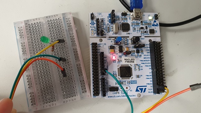
We will use a NUCLEO STM32L053R8 board to show as configure DAC with STCube. In this modality we can drive DAC to on/off a LED, to generate a reference voltage, etc.
#Ide for stm32 nucleo board code#
The conversion consists in sending the voltage corresponding to the code applied to the input to the output of the converter. the value proportional to the code implied in the binary word). The operating criterion of a DAC is simple: in fact, it is sufficient to have a succession of as many voltages as there are convertible codes, obtained for example by means of a weighted resistance network (i.e. This means that the devices to which the analog signal produced by a DAC is sent must filter it with a low-pass characteristic (integrating action). Since the input binary words represent a succession of finite codes, the voltage coming out of a DAC cannot be continuous over time but is made up of as many levels as the converted codes are. A Digital to Analog Converter( DAC) performs the task of converting digital words of n bits into voltages whose amplitude will be proportional to the value of the code expressed by the words themselves.


 0 kommentar(er)
